The Chimney Sweep Online Fireplace, Woodstove, Gas Stove and Barbecue Shop

The Chimney Sweep Online Fireplace, Woodstove, Gas Stove and Barbecue Shop

| A: Minimum Fireplace Opening Width...................................................................
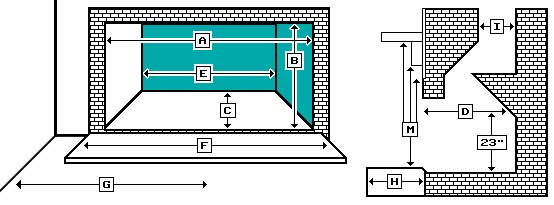
B: Minimum Fireplace Opening Height................................................................... C: Minimum Fireplace Depth at Floor.................................................................... D: Minimum Fireplace Depth at 20" above Floor................................................... E: Minimum Fireplace Width at 17" Depth............................................................. F: Minimum Hearth (Floor Protection) Width......................................................... G: Centerline of Fireplace Opening to Combustible Sidewall or Trim...................... H: Minimum Hearth (Floor Protection) Depth ........................................................ I : Minimum Flue Size Needed to Accomodate Intake/Exhaust Flex........................ M:Minimum Height from Hearth to Combustible Mantel ........................................ Surround Panel Sizes: Standard Face Plate: 38"W x 26"T Extra Large Face Plate: 42"W x 28"T |
32" 22" 18" 18" 21" 0" 18" 0" 5" x 8" 35" |
INSTALLING THE INTAKE / EXHAUST LINER KIT | ||
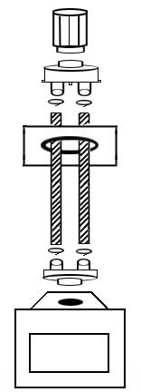
 | Standard Aluminum Flex Liner Kit:Stretch the 3" intake liner and 4" exhaust liner to the required length (up to 35'), and attach the two lengths to the intake and exhaust ports on the top adapter box with silicone sealant and sheet metal screws or pipe clamps. Silicone the sealer plate to the top of the chimney. Fish the lengths down through the plate and the fireplace damper below. Attach the top adapter box to the top sealer plate with sheet metal screws and twist-lock the rain cap on. Down below, use clamps or screws and silicone sealant to attach the liners to the intake and exhaust ports on the insert. | |
GAS HOOKUP: A 1/2" standard pipe thread gas fitting exits the insert near the bottom of the left side. Use a flex connector to make the gas connection while the insert is on hearth, attach the surround panels, then slide the insert into place.NOTE: THIS DIRECT VENT GAS APPLIANCE COMES WITH DETAILED, STEP BY STEP INSTRUCTIONS FOR DO-IT-YOURSELF INSTALLATIONS. TO VALIDATE YOUR WARRANTY AND ENSURE OPTIMUM SAFETY AND PERFORMANCE, HOWEVER, FINAL SETUP ADJUSTMENTS AND INITIAL FIRING MUST BE ACCOMPLISHED BY A TRAINED GAS SERVICE TECHNICIAN. CONSULT YOUR GAS SUPPLY COMPANY FOR A LIST OF RECOMMENDED SERVICE TECHNICIANS IN YOUR AREA. |
