The other day I posted a question about Return to storage piping method.
https://www.hearth.com/econtent/index.php/forums/viewthread/78772/
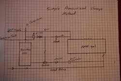
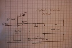
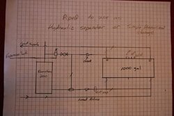
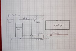
I drew 3 different methods I am considering for piping
1. The Simple Pressurized storage Method
2. The Hydraulic Separator Method
3. Combination, Which is more pipe and a few more valves but I think it would allow me to use either style piping depending on the time of year or what I am heating.
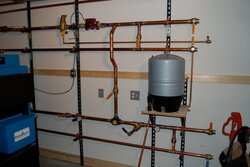
Please provide any comments or suggestions on Which method you feel is best. I have also included the near boiler piping picture.
gg
https://www.hearth.com/econtent/index.php/forums/viewthread/78772/
I drew 3 different methods I am considering for piping
1. The Simple Pressurized storage Method
2. The Hydraulic Separator Method
3. Combination, Which is more pipe and a few more valves but I think it would allow me to use either style piping depending on the time of year or what I am heating.
Please provide any comments or suggestions on Which method you feel is best. I have also included the near boiler piping picture.
gg