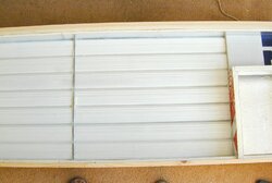
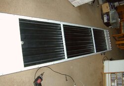
As part of my ongoing project to reduce wood consumption, I've just installed another solar air heater, designed and built incorporating some of the concepts that I learned from woodstoves over the years. It's a simple design that uses aluminum downspout tubes as the absorber and heat exchanger. That in itself is nothing new; downspout tubes have been used in solar heaters for a few years and have proven to be a good choice for horizontally-displaced air heaters. But the way this one works addresses the major shortcomings of earlier designs.
Previous tube designs were basically insulated boxes with tubes attached to the back and glazing on the front. Air flows through half of the tubes in one direction, then reverses through the other half. And therein lies the two major problems. Attaching the tubes directly to the back, separated only by an R6 insulating board, creates a heatsink directly from the heat exchangers to the outdoors, cooling them off. And the long path length that the air travels through is not an efficient use of the exchanger surface area, requiring high air velocity through the system to achieve reasonable efficiency.
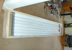
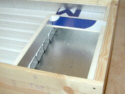
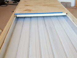
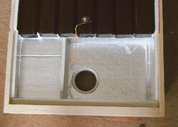
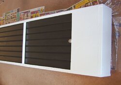
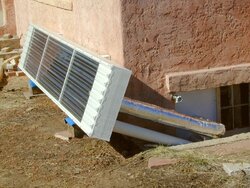
Both problems can be solved with minimum added complexity by suspending the tubes away from the back, using that channel to rout the incoming air to the other end, and then flow it through all of the tubes at once in parallel. The heat that was previously conducted through the back now preheats the incoming air, and air velocity is cut in half or better.
All of the materials needed to build this can be found at your local big box store, total cost around $200.
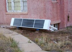
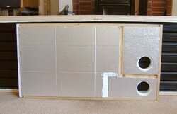
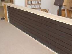
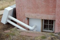
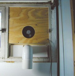
This is what the finished heater looks like, vented into a basement window to heat my lab (yes, the duct tubes will be insulated at some point...). The dimensions are 12' L x 2' H x 8" D. The heat exchanger area is 10' x 2', which will heat 200-400 sq ft. depending on the insulation, height, etc. I'm guessing it will reduce my wood use downstairs by a third or more.
A snap switch is built in for fan control, turning on at 110F and off at 90F, making it completely automatic.
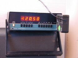
Today is the first day I'll be able to operate and test it - should be fun!
Previous tube designs were basically insulated boxes with tubes attached to the back and glazing on the front. Air flows through half of the tubes in one direction, then reverses through the other half. And therein lies the two major problems. Attaching the tubes directly to the back, separated only by an R6 insulating board, creates a heatsink directly from the heat exchangers to the outdoors, cooling them off. And the long path length that the air travels through is not an efficient use of the exchanger surface area, requiring high air velocity through the system to achieve reasonable efficiency.
Both problems can be solved with minimum added complexity by suspending the tubes away from the back, using that channel to rout the incoming air to the other end, and then flow it through all of the tubes at once in parallel. The heat that was previously conducted through the back now preheats the incoming air, and air velocity is cut in half or better.
All of the materials needed to build this can be found at your local big box store, total cost around $200.
This is what the finished heater looks like, vented into a basement window to heat my lab (yes, the duct tubes will be insulated at some point...). The dimensions are 12' L x 2' H x 8" D. The heat exchanger area is 10' x 2', which will heat 200-400 sq ft. depending on the insulation, height, etc. I'm guessing it will reduce my wood use downstairs by a third or more.
A snap switch is built in for fan control, turning on at 110F and off at 90F, making it completely automatic.
Today is the first day I'll be able to operate and test it - should be fun!